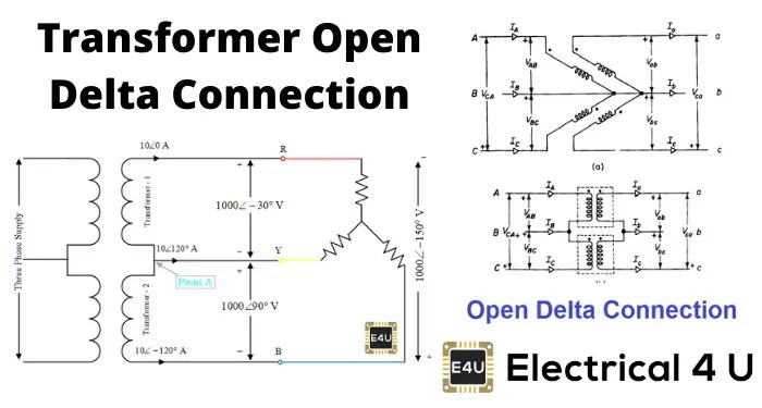
When it comes to electrical systems in the home, safety should be the number one priority. That’s why it’s essential that homeowners understand the basics of three-phase connection post house wiring diagrams. Whether you’re a novice or an experienced electrician, having a working knowledge of how these diagrams are organized and how they’re used will help you stay safe and get the job done right.
Three-phase connection posts are used to connect three-phase systems in a home’s electrical system. This includes large appliances such as air conditioners, refrigerators, and dryers, as well as lighting circuits, outlets, and other electrical installations. These posts are typically located on the outside of the home, near the main electrical panel.
A three-phase connection post house wiring diagram is a visual representation of the electrical connections between the three phases of power in the home. It’s made up of three circles, each representing one of the three phases. The circles are connected by lines, which represent the wires that carry electricity from the main panel to the various electrical components. Each circle also contains symbols that indicate the type of component connected to it. For example, a light bulb symbol might indicate that a light switch is connected to the phase.
To safely install a three-phase connection post, it’s important to understand the rules of the National Electrical Code (NEC). This code outlines the basic requirements for wiring and installing electrical systems in the home. These requirements include the types of materials that must be used, the size of the wires, and the spacing between them. It’s important to read the entire code before beginning any type of wiring project.
When it comes to understanding how to read a three-phase connection post house wiring diagram, it’s important to start at the top. The diagram begins with the utility pole, which is the source of the power. From there, the diagram shows each of the three phases, as well as the components connected to them. If a component is not connected to a phase, it will be indicated with a “no connection” symbol.
Understanding how to read a three-phase connection post house wiring diagram is essential for anyone working with electrical systems. Having a working knowledge of the NEC and following its requirements is key to staying safe when working with electricity. By understanding the diagram and the components connected to it, you can ensure that your wiring project is done correctly and safely.

Wazipoint Engineering Science Technology Star Delta Starter Line Diagram And Its Working Principle

Simple Ways To Identify Single Phase Or 3 10 Steps

Open Delta Transformer Connection Calculation Diagram V Electrical4u
Three Phase Motor Connection Diagram And Wiring Procedure Etechnog

Power Factor Meter Diagram Working Types Electricalworkbook

House Wiring Diagram Everything You Need To Know Edrawmax Online

Three Phase Electric Power Driven Electroluminescent Devices Nature Communications
Three Phase Motor Connection Diagram And Wiring Procedure Etechnog
What Is Changeover Switch Wiring And Connection Diagram Etechnog
Wiring Diagram Explore Facebook
Electrical Engineer Home Facebook

How To Connect A Three Phase Motor In Star And Delta Connection Instrumentation Control Engineering

What Is The Difference Between 1 Phase 2 And 3 Power

Simple Ways To Identify Single Phase Or 3 10 Steps

Three Phase Transformer Connections Wiring Diagrams Included Electrical4u

Difference Between Single Phase Three Ac Power Supply

Single Three Phase Transformer Vs Bank Of Transformers Electrical4u

What Is An Electrical Diagram And Are The Diffe Types Of Diagrams Instrumentation Control Engineering
Ct And Pt Connection Diagram Explained Etechnog


