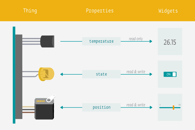
The Internet of Things (IoT) is revolutionizing our world, and Arduino diagrams are an integral part of this technological revolution. Arduino Diagrams provide a visual representation of how all the different components of an IoT system interact with each other. By understanding the basics of Arduino Diagrams, you can start building your own IoT projects with ease.
Arduino Diagrams are essentially schematic diagrams that show how different pieces of hardware and software interact with each other. These diagrams can be used to understand the overall structure of a complex IoT system. They often contain circuit elements such as resistors, capacitors, transistors, and microcontrollers, as well as other components such as sensors, actuators, and displays.
At the heart of all Arduino diagrams is the Arduino microcontroller. This is the small device that is responsible for controlling all the other components in the system. It is programmed using the Arduino programming language and is typically connected to other components through GPIO pins, which allow it to receive input from sensors and send output to actuators.
In addition to the microcontroller, Arduino diagrams also contain various other components such as sensors, actuators, and displays. These components can be used to sense the environment, actuate motors and lights, and display data. They are connected to the microcontroller through GPIO pins, and the microcontroller is programmed to read the values from the sensors and actuate the actuators accordingly.
Once you have a basic understanding of the components and connections involved in an Arduino Diagram, you can use them to design and build your own projects. With the help of the Arduino programming language and open source libraries, you can easily create complex systems and connect them to the internet. This allows you to collect data from the environment, actuate motors and lights, and display it on a screen. All this is possible thanks to the power of Arduino diagrams.
If you are looking to get started with your own IoT projects, understanding Arduino diagrams is essential. By learning how to read and interpret these diagrams, you can quickly move from concept to implementation. With the help of Arduino diagrams, the possibilities of what you can do with the Internet of Things are endless.

Guide For Interfacing Relay With Arduino The Iot Projects

10 Of The Best Iot Projects Using Arduino Tech Trends

Home Automation With Arduino Iot Cloud Using Esp8266

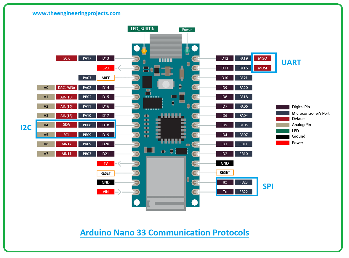
Arduino Nano 33 Iot Pinout Specs Schematic Detail Board Layout
Nano 33 Iot Arduino Doentation

Arduino Iot Cloud Officially Sees Light Of Day

Iot Based Electricity Energy Meter Using Esp12 And Arduino

Tutorial Arduino Schematic Esp8266 Iot Security

Stick Based On Iot Contains The Arduino Scientific Diagram

Home Automation With Arduino Iot Cloud Using Esp32

Iot Based Health Monitoring System Arduino Project Diy Electronics Projects

Getting Started With Arduino Cloud Iot Connect Esp8266 To
The Arduino Nano 33 Iot

Introduction To Arduino Nano 33 Iot The Engineering Projects

Getting Started With Arduino Nano 33 Iot Microcontroller Development Board Pinout Schematic Example Programs Circuitstate Electronics

Create Home Automation With Arduino Iot Cloud Mouser

Smart Dustbin Using Esp8266 And Arduino Iot Electro Programics

Pool Water Monitoring 3 Getting Started With Arduino Iot Cloud Blog Just Encase Element14 Community