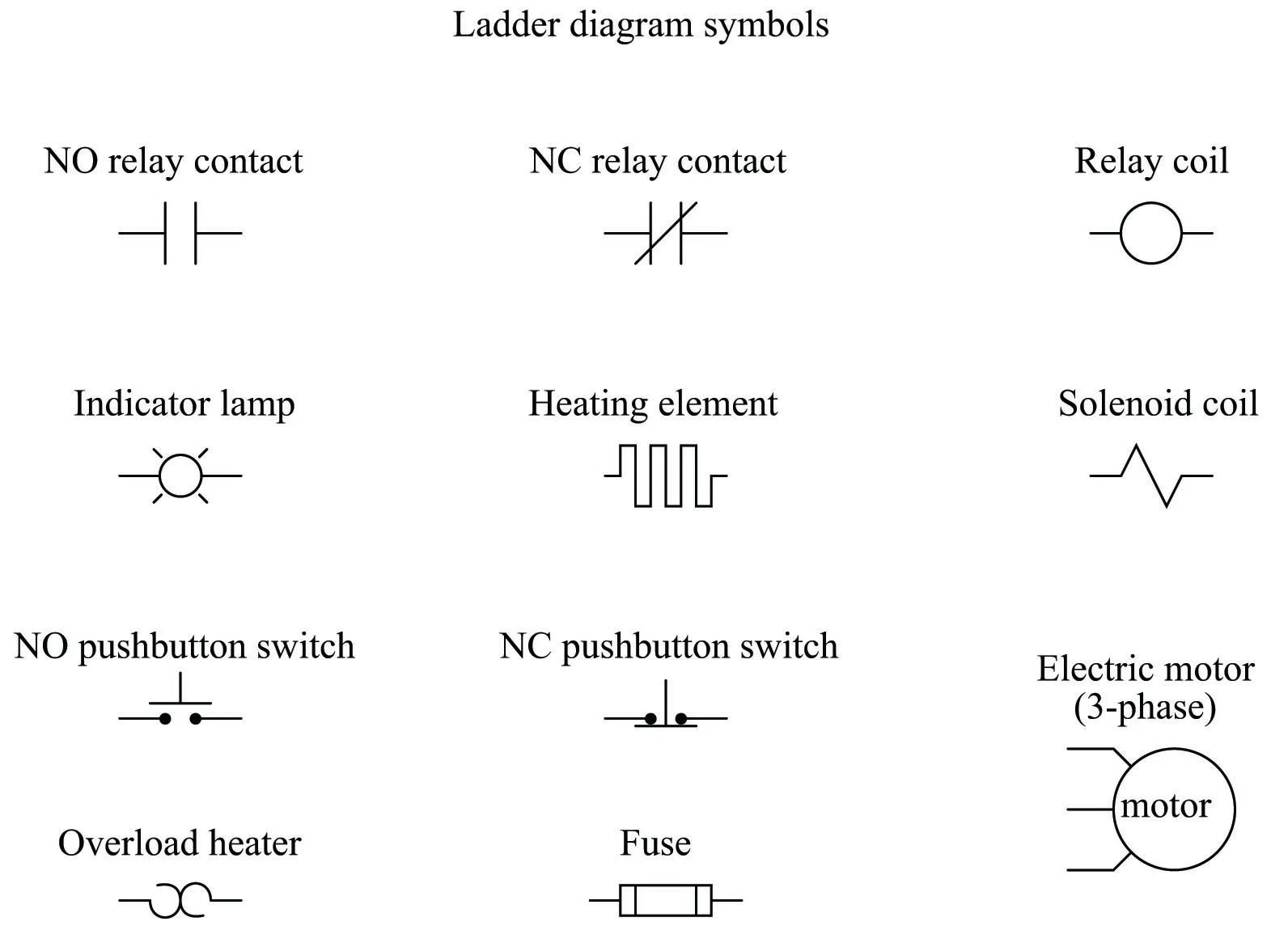
When it comes to electrical wiring and circuit diagrams, one of the most important symbols you’ll need to know is the contactor symbol. This symbol is used to represent an electrical contactor, which is an electrically operated switch that controls the flow of power within a circuit.
A contactor symbol consists of two lines, with a gap between them, representing the contactor’s on/off operation. The gap between the lines indicates the open position of the contactor, while the lines themselves represent the closed position. The contactor symbol can also include additional details, such as its rated voltage, amperage rating, and number of poles (or contact points).
Contactor symbols are typically found in wiring diagrams and are used to provide an easy-to-understand visual representation of how a circuit is wired. By understanding contactor symbols, you can quickly diagnose and repair circuits, identify potential problems, and determine the correct order of operation.
Contactor symbols are essential for anyone who works with electrical wiring, whether they’re an engineer, electrician, or DIY enthusiast. With a basic understanding of these symbols, you’ll be able to confidently tackle any wiring project.
What Is The Symbol Of A Contactor Quora

Master Switch Wiring Diagram
Electrical Engineering Magnetic Facebook

Contactors And Relays Construction Operation

Dol Starter Scheme And Wiring Diagram Electric Guider

Relay Circuits And Ladder Diagrams Control Systems Automation Textbook

Circuit Diagrams Of Safety Components Technical Guide Singapore Omron Ia
Nema And Iec Schematic Diagram Comparisons Mz081001en

Components Symbols And Circuitry Of Air Conditioning Wiring Diagrams Part 2

Wiring Diagrams Explained How To Read Upmation

European Schematics Control Parts

Electrical Contactor Connection And Wiring 1 Bbe

How To Read The Electrical Diagram And What Are Symbols Involved In It Instrumentation Control Engineering

Components Symbols And Circuitry Of Air Conditioning Wiring Diagrams Part 2

How To Read The Electrical Diagram And What Are Symbols Involved In It Instrumentation Control Engineering

Electrical Contactor Connection And Wiring 1 Bbe

Single Phase Motor Connection With Magnetic Contactor Wiring Diagram Electrical And Electronics Technology Degree

Electrical Symbols Switches And Relays

Symbols In Electrical System Layout Scientific Diagram
