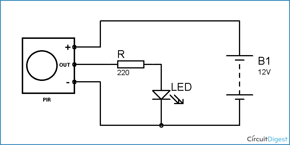
A wiring diagram for a zinc PIR (passive infrared) sensor is essential for those looking to install one of these devices. These sensors can be used for a variety of applications, from home security to motion detection on industrial machinery. Understanding the wiring diagram for a PIR sensor is key to ensuring that it is installed correctly and functions properly.
For starters, a PIR sensor consists of two main components: the sensing element and the detection circuit. The sensing element is composed of two small parts, a zinc diaphragm and an optical filter. The diaphragm is highly sensitive to changes in temperature and when the temperature reaches a certain level, it causes the optical filter to vibrate. This vibration is what triggers the detection circuit.
The detection circuit is responsible for turning the signal generated by the sensing element into an electrical current. This current is sent to a control unit, which can then be used to activate an alarm or other device. To make this process work, the detection circuit needs to be wired correctly.
The wiring diagram for a zinc PIR sensor is relatively straightforward. First, the sensing element is connected to a power source (usually the mains) via two wires. This provides the voltage necessary for the diaphragm to vibrate when the temperature rises. Next, the wires from the sensing element are connected to the detection circuit. The detection circuit is then connected to the control unit. Finally, the control unit is connected to the alarm or other device.
If all the connections are correct, then the PIR sensor should be ready to go. It is important to note, however, that the wiring diagram for a zinc PIR sensor may vary depending on the model being used. It is also important to ensure that the voltage supplied is appropriate for the sensor and that the wires have been connected correctly.
In conclusion, the wiring diagram for a zinc PIR sensor is essential for anyone looking to install one of these devices. It is important to understand the components involved and how they interact with each other in order to ensure that the PIR sensor is functioning properly. If all the connections are made correctly and the voltage is appropriate, then the PIR sensor should be ready to go.

How To Build A Motion Sensor Light Circuit

Testing A Pir Motion Sensor Adafruit Learning System
Offers Of Asaj Sp Z O Lighting Ings Merxu

Motion Sensor Wiring With Switched Override Feature

Pir Sensor Security Light Switch
Ebdspir Hb Dd Product Guide

How To Install Motion Sensor Light Full Guidelines
Ins Zn 25154 St05b

360 Ceiling Pir Single Sensor Ip20 Surface Toolstation

Pir Sensor Based Motion Detector Circuit Diagram
Zinc Thea Indoor White Microwave Recessed Sensor 360 Motion Sensors Fix Com

180 Mini Pir Sensor Major Tech
Operation Manual
Conf By Possible Conflict Between Pir And Photocell Fix Community Forum

Basics Of Surge Esd And Protection Components Panasonic

Zinc Zn25152 User Instructions Pdf Manualslib

1l Ps041 360 Ceiling Mount Occupancy Sensor 1 Leap Technologies

Gravity Analog Electrical Conductivity Sensor Botland Robotic

