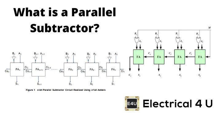
In the world of electronics and engineering, binary subtractors are essential components for computing operations. A 4-bit binary subtractor circuit diagram is a graphical representation of the logic used to perform binary subtraction. It is one of the most important building blocks of digital logic circuits and is used in a wide variety of applications.
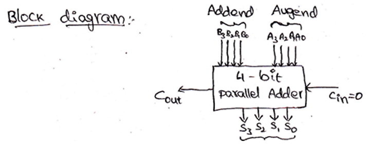
The 4-bit binary subtractor consists of four 1-bit full adders connected in series. This allows the subtractor to handle four bits of information at a time. The full adder is a combinational circuit which adds two binary numbers and generates a sum output and a carry output. The full adder takes three inputs, the two binary numbers to be added and a carry bit from the previous stage. The sum output of each stage is sent to the next stage and the carry output is added to the next higher order bit of the binary number.
The 4-bit binary subtractor is used to perform subtraction between two 4-bit binary numbers. The inputs to the subtractor are two 4-bit binary numbers, the minuend and the subtrahend. The subtractor outputs the difference between the two inputs as a 4-bit binary number.
The 4-bit binary subtractor can be implemented using a logic circuit diagram. The diagram shows the inputs and outputs of the subtractor and how they are connected to the logic gates. The logic gates used in the subtractor are AND, OR, XOR, and NOT gates. The logic circuit is designed using the Boolean algebraic equations for the logic gates.
The 4-bit binary subtractor is used in a wide variety of applications such as arithmetic logic units (ALUs), computer processors, and logic circuits. It is also used in scientific applications such as digital signal processing. The subtractor is an important component of the digital logic circuit and it is used in many different types of computers and electronic devices.
The 4-bit binary subtractor is a powerful tool for performing binary subtraction operations. With its simple logic circuit diagram, it can be easily understood and implemented in various applications. It is an essential building block for digital logic circuits and is used in a wide variety of applications.

Binary Subtraction With Two S Complement

Parallel Subtractor Electrical4u
2 4 Binary Adder Subtractor Addition And Subtraction Are Two Basic Arithmetic Operations That Must Be Performed By Any Dig
Experiments No 6 11 Amittal

How To Design A Four Bit Adder Subtractor Circuit Ee Vibes

4 Bit Serial Adder Subtractor With Parallel Load Altynbek Isabekov
4 Bit Binary Adder Subtractor Multisim Live

Digital Logic

Exploreroots Parallel Subtractor Borrow Propagate Look Ahead

Chapter 11 Laboratory Experiment Ppt Online

4 Bit Binary Adder Subtractor Tinkercad

Full Subtractor Circuit And Its Construction

Module Ii Binary Subtractor Ppt Online

Full Subtractor Circuit And Its Construction

Figure 16 7 Shows A Four Bit Binary Adder Subtractor Circuit Configured Around Parallel Type Number 7483 And Quad Two Input Ex Or Gate 7486 The Arrangement Works As An
Chapter 1 Digital Circuits

N Bit Parallel Adders 4 Binary Adder And Subtractor

Solved Use Adder Subtractor Circuit Add 4 Bit Signed Binary Numbers B Step Show Bits Ad Q40780809 Coursehigh

Cs 105 Digital Logic Design Chapter 4 Combinational

Parallel Adder And Subtractor Block Diagram