If you’ve ever tried to add two 4-bit binary numbers, you know it can be a challenge. But with the help of a 4 bit parallel adder circuit diagram, you can make the process much easier. In this article, we’ll explain what a 4 bit parallel adder circuit diagram is, how it works, and why it’s so useful for adding two 4-bit binary numbers.
A 4 bit parallel adder circuit diagram is a type of digital circuit that helps you to add two 4-bit binary numbers together. The circuit consists of two 4-bit inputs, an output, and a few logic gates. When two 4-bit binary numbers are placed in the circuit, the logic gates are used to determine the sum of the two binary numbers.
The way the circuit works is actually quite simple. Each logic gate performs a specific operation on one of the two input bits. For example, if the first input bit is “1” and the second input bit is “0”, the logic gate will perform a function that results in the output bit being “1”. This is repeated for all four input bits, and the resulting sum of the two binary numbers is computed.
A 4 bit parallel adder circuit diagram is a great tool for anyone who needs to quickly and accurately add two 4-bit binary numbers. It’s also a great way to learn the basics of digital circuits, as it provides a visual representation of how the logic gates work together to compute the sum of two binary numbers.
Overall, a 4 bit parallel adder circuit diagram is a great way to quickly and accurately add two 4-bit binary numbers. It’s easy to set up and understand, and it can help you learn the basics of digital circuits. If you’re looking for a way to quickly and accurately add two 4-bit binary numbers, a 4 bit parallel adder circuit diagram may be just what you need.

4 Bit Parallel Adder Using Full Tinkercad
4 Bit Parallel Adder 8 Full Binary Arithmetic Circuits Notes Study Digital

Design Of Arithmetic Circuits Adders Subtractors Bcd Ppt

A Bit Parallel Ripple Carry Adder In Serial B Scientific Diagram

Answers To Selected Problems In Chapter 5 Cosc3410

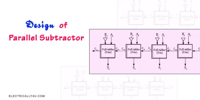
Design Of Parallel Subtractor
9 Four Bit Adder Mr Bridger S Web Page
How To Make An 8 Bit Parallel Adder And Subtractor With Only 2 74ls83 1 74ls86 Full Adders 4 Xor Gates Quora

Coa Binary Adder Javatpoint

4 Bit Binary Adder Circuit Discussion With Example

Ripple Carry Adder 4 Bit Gate Vidyalay

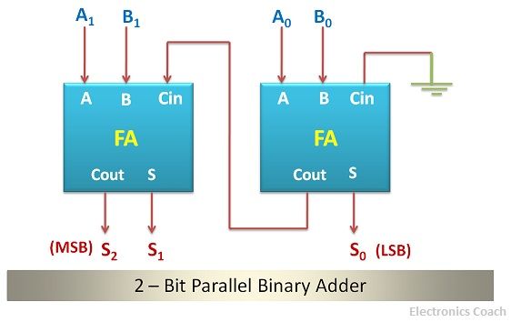
What Is Parallel Binary Adder 2 Bit And 5 Electronics Coach

Parallel Adder How It Works Types Applications And Advantages

Parallel Adder Or Subtractor Electrical4u

4 Bit Ripple Carry Adder Vhdl Code

4 Bit Serial Adder Subtractor With Parallel Load Altynbek Isabekov

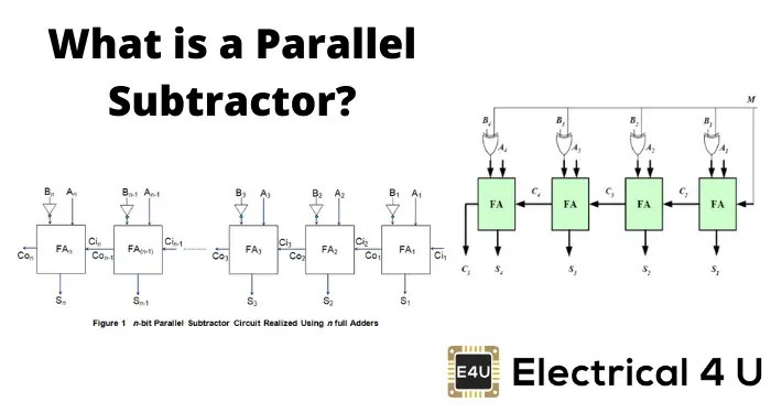
Parallel Subtractor Electrical4u

Circuit Diagram Of 4 Bit Multiplier To Following The Addition Scientific

Design Of Parallel Adder
Parallel Adder