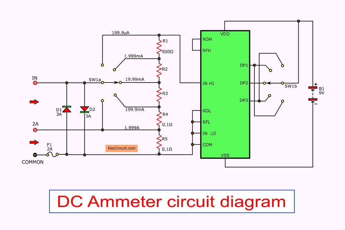
Ammeter Circuit Diagrams: Understanding Power Flow in Your Home
Do you know how much electricity your home is consuming? If not, it’s time to learn. A basic knowledge of ammeter circuit diagrams can help you understand the power flow in your home and save you money in the long run.
An ammeter circuit diagram is a visual representation of the relationship between electrical components in an electrical system. It shows how much current is flowing through each component, as well as the voltage potential and resistance. This information is essential to ensure that your electrical system is running efficiently and safely.
To understand how an ammeter works, consider the following example. In a typical home, there are many different types of appliances, lights, and other electrical devices. Each of these devices has its own electrical circuit, and each circuit has a unique ammeter circuit diagram.
In each circuit, the ammeter measures the amount of current flowing through the circuit. The higher the current, the more power is being consumed. This is why it’s important to understand how much power each appliance or device is consuming in order to determine which ones are consuming the most.
When looking at an ammeter circuit diagram, you’ll notice that it’s divided into two parts: the primary and secondary circuits. The primary circuit is responsible for supplying the energy needed to run the electric devices while the secondary circuit is responsible for monitoring the current flow.
The primary circuit usually consists of a main panel, power supply, and other components. The secondary circuit consists of the ammeter itself and its associated components. The ammeter measures the amount of current flowing through the circuit, and this information is fed back to the main panel.
Once you understand the basics of an ammeter circuit diagram, it’s time to start understanding how to read it. Reading an ammeter circuit diagram can be tricky, but it’s not impossible. Most diagrams are labeled with colors to indicate the specific components within the circuit, and there are usually arrows pointing to the direction of the current flow.
Once you’ve mastered the basics of ammeter circuit diagrams, you’ll have a better understanding of how your home’s electrical system works. This knowledge can help you make smart decisions about how much power you use and save you money in the long run. So don’t hesitate to take the time to learn about ammeter circuit diagrams and the power flow in your home.

A An Equivalent Circuit Of The Ammeter In Fig 1 B Simplified Scientific Diagram

Question Determining The Circuit Diagram That Represesnts Ammeter Nagwa

Question Identifying The Connection Of Ammeters In Circuits Nagwa

Ammeter Design

Ammeter

Dc Ammeters

Dual Lcd Voltmeter Ammeter 0 100 Vdc 10 A Dc Atmega8 Electronics Projects Circuits

Ammeter Voltmeter Transducer Meters Wire Diagram

Connecting Voltmeter And Ammeter Under Repository Circuits 31474 Next Gr
Lesson Explainer Ammeters Nagwa

Ammeter Electric Cur Wiring Diagram Wikipedia Electrical Network Flow Angle White Png Pngegg

Digital Panel Ammeter Wiring Diagram

What Is Ammeter Shunt Definition Resistance Calculation Circuit Globe

8 5 Ammeter Impact On Measured Circuit

Electronic Voltmeter Ammeter Circuit Pic16f876 Lcd Picbasic Electronics Projects Circuits

A Draw Ammeter Symbol On This Circuit Diagram Where It Would Measure The Cur Through Electric Motor Teachernotes4u

Ammeter Working Principle Circuit Diagram Types And Applications

Digital Voltmeter And Ammeter Circuit Module Under Repository Circuits 24854 Next Gr

Ammeter And Voltmeter Circuit Diagram Cur Electricity 12 Jee Neet

Digital Multimeter Circuit Using Icl7107