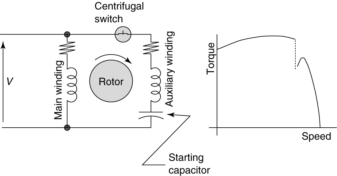
The circuit diagram for a capacitor start motor is an important tool for understanding how these motors work and how they are wired. A capacitor start motor is a type of motor that uses a capacitor to help the motor start, and it is commonly used in applications such as air conditioners, refrigerators, and other small appliances. Understanding the circuit diagram for a capacitor start motor can help you troubleshoot problems and make sure your motor is working properly.
Capacitor start motors have several advantages over standard motors. They require less energy to start up, which helps reduce electricity costs. They also produce less heat and vibration during use, which means they are quieter and more efficient. The capacitors used in these motors also provide a higher starting torque, which makes them ideal for applications where quick starts are needed.
In order to understand the circuit diagram for a capacitor start motor, it is important to first understand the basic principles of electricity. Electricity flows in a circular pattern from the source to the load and back. In the case of a capacitor start motor, the capacitor is used to store the energy needed to start the motor. The capacitor stores the energy and then releases it when the motor is turned on.
When looking at the circuit diagram for a capacitor start motor, you will see several components. These include the capacitor, the motor, the coils, the commutator, and the power supply. The capacitor is connected to the motor and the power supply. The motor then uses the stored energy from the capacitor to start. The coils and the commutator are used to switch the direction of the current from the capacitor to the motor.
The best way to understand the circuit diagram for a capacitor start motor is to look at a real-life example. You can find examples of these diagrams online, or in manuals that come with the motor. If you are having trouble understanding the circuit diagram, you can also consult with a professional electrician or mechanic. They can help you understand the wiring and troubleshoot any issues you may have.
Understanding the circuit diagram for a capacitor start motor can save you time and money. By understanding how these motors work, you can make sure your motor is running properly and efficiently. This can help ensure that your motor is running at its peak performance, so that you can get the most out of your appliance.

What Is Capacitor Start And Run Induction Motor Electricalworkbook

Ac Single Phase Motors Part 2

Single Phase Motor Wiring Diagram And Examples Wira Electrical

Electric Motor Diagrams

Capacitor Start Motors Diagram Explanation Of How A Is To Single Phase Motor Bright Hub Engineering

Single Phase Motor Wiring Diagram And Examples Wira Electrical
Single Phase Motor Connection Diagram And Wiring Procedure Etechnog

Capacitor Start Induction Motor Its Phasor Diagram Characteristic Applications Circuit Globe

Centrifugal Switch What Is It And How Does Work Electrical4u

What Is Capacitor Run Induction Motor Fan Electricalworkbook

The Capacitor Start Split Phase Motor

Split Phase Hermetic Motor Windings And Terminals

What Is A Split Phase Induction Motor Its Applications Circuit Globe

Single Phase Motor Starting Voltage Disturbance

Capacitor Start Run Motors

Types Of Single Phase Induction Motors Split Capacitor Start Run Electrical4u

Types Of Single Phase Induction Motors Motor Wiring Diagram Electrical Academia

Single Phase Hermetic Motors
Electrical Tech Note 103

Types Of Single Phase Induction Motors Motor Wiring Diagram Electrical A2z
