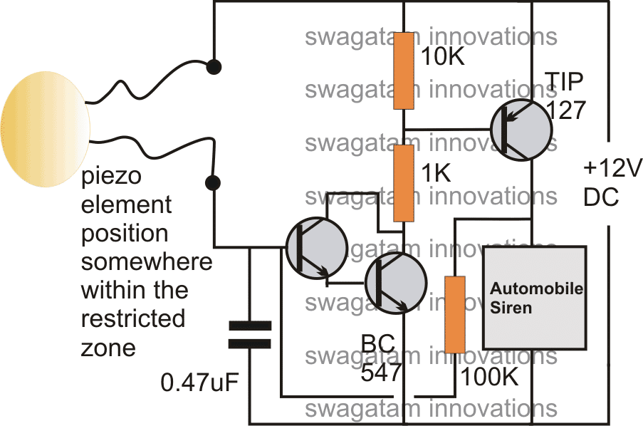
The safety and security of your home is of the utmost importance. A house safety alarm system can provide an added layer of protection for you and your family. But before you install one, it’s important to understand the circuit diagram of a house safety alarm.
A typical house safety alarm circuit diagram includes a power source, an alarm, a switch, and a sensor. The power source is typically a battery or an electrical outlet. The alarm is the component that makes a loud sound when the system is tripped. The switch is used to turn the system on and off. And the sensor is the component that detects any intrusion and triggers the alarm.
The basic components of a house safety alarm system are connected in a specific order. First, the power source is connected to the alarm. Then, the switch is connected to the power source. Next, the sensor is connected to the switch. Finally, the alarm is connected to the sensor. This creates a complete circuit which is powered when the switch is turned on.
When the sensor detects an intruder, it triggers the switch, which in turn triggers the alarm. The alarm will sound until the switch is turned off. It’s important to note that the alarm can be triggered by a variety of things, including movement, sound, light, or vibration. Depending on the type of system installed, you may also be able to add additional sensors, such as window or door sensors.
Having a house safety alarm system in place is an important part of keeping your home and family safe. Understanding the circuit diagram of a house safety alarm system is essential to making sure your system is properly set up and functioning properly. If you need help understanding the circuit diagram, be sure to consult with an experienced electrician or alarm system installer.

Burglar Alarm Project With Circuit Diagram

Mini Laser Security Alarm System Using Bc547 My Project Ideas

Product Cctvsolutionssrilanka

Infrared Ir Based Security Alarm Circuit Using 555 Timer Ic Lm358

Circuit Diagram Of The Alarm Unit Scientific

Security Alarm Circuit With High Power Siren Diagram And More

Simplest Theft Alarm Circuit Gadgetronicx
Alarm Circuit The Construction And Working Principle

Simple Home Alarm

5 Simple Alarm Circuits For Protecting Your Home Office From Theft Homemade Circuit Projects
A Simple And Reliable Touch Sensitive Security System

Home Security System With Laser And Ldr

Safer Security System Alarm Circuit Scheme
How Burglar Alarms Work Howstuffworks

5 Simple Alarm Circuits For Protecting Your Home Office From Theft Homemade Circuit Projects

Home Security System Using Arduino Uno In Proteus The Engineering Projects

Laser Security Alarm Circuit

Sms Home Alarm System