When it comes to wiring projects, a CT Wiring Diagram can make all the difference. It is one of the most important tools for electricians, allowing them to quickly and accurately connect wires, fixtures, and components in any wiring project. As such, having a comprehensive understanding of CT Wiring Diagrams is essential for anyone involved in the electrical trades.
At its most basic level, a CT Wiring Diagram provides a visual representation of how electrical components are connected. It shows the direction of current flow, the type of wiring used, and the order in which the various components are wired together. Each line on the diagram corresponds to a physical wire, and each junction is represented by a symbol that indicates the type of connection.
In order to read and interpret a CT Wiring Diagram, you must first understand the basics of electricity. Knowing the polarity of a wire is essential, as it affects the direction of the current flow. You should also be familiar with the different types of wiring, such as twisted pair, shielded, and unshielded, as well as the different colors associated with each type. Color coding makes it easier to identify the various parts of a wiring project.
Once you have a basic understanding of how electricity works, you can begin to read a CT Wiring Diagram. Start by identifying the different symbols on the diagram, such as the lines, junctions, and symbols that represent the type of connection. Then, trace the path of the current along the wires, using the color coding to help you identify the different components. Once you have traced the current, you can identify the various components and their connections.
It is important to note that there are several different types of CT Wiring Diagrams, so it is important to ensure that you are using the right one for your particular project. Additionally, some diagrams may require additional information, such as the size of the wiring or the voltage rating of certain components. As such, it is important to always consult the manufacturer’s instructions before beginning any wiring project.
By taking the time to learn how to read and interpret a CT Wiring Diagram, you can save yourself time and money when completing any wiring project. This knowledge can also help you identify potential problems before they become an issue, allowing you to address them quickly and efficiently. With the right knowledge and skills, you can confidently tackle any wiring project with ease.

Split Core Cur Transformer Solution Acrel

Lt Ac Three Phase Four Wire Panel Mounted Static Kwh Meter Manualzz

The Electrics Find Your Exit

Wiring Diagram For Cur Transformer With Matching Circuit Scientific

Metering In Today S World Ppt
How To Properly Short A Ct Shorting Block Faqs Schneider Electric South Korea

Ct Wiring Question Electric Motors Generators Engineering Eng Tips

Cur Transformer Physical Wiring Diagram Knowledge Dalian Huayi Electric Power Appliances Co Ltd

Cur Transformer Physical Wiring Diagram Knowledge Dalian Huayi Electric Power Appliances Co Ltd

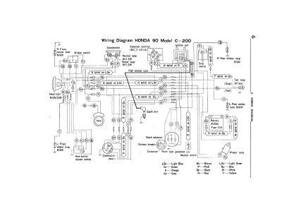
Wiring Schematic For Honda Ct200
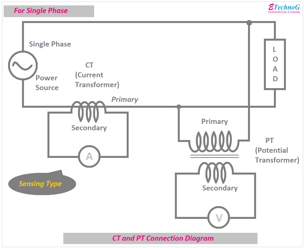
Ct And Pt Connection Diagram Explained Etechnog

47 Ways To Wire Your Power Meter Wrong Kele Com
Installation Manual A1140 Three Phase Meter Wc Or Ct Ldc
Explanation Of Voltage And Cur Input Wiring Diagram For Ion8600 Form 9 9s 3 Wire Wye 3pts 2cts Schneider Electric India
What Is Core Balance Cur Transformer Cbct Diagram Application Etechnog

Summation Cur Transformer Calculations Electrical4u

The Ctb 6 Cur Transformer Secondary Overvoltage Protection
Installation Manual Three Phase Energy Meter

Wiring Diagram In Solar Pv System

