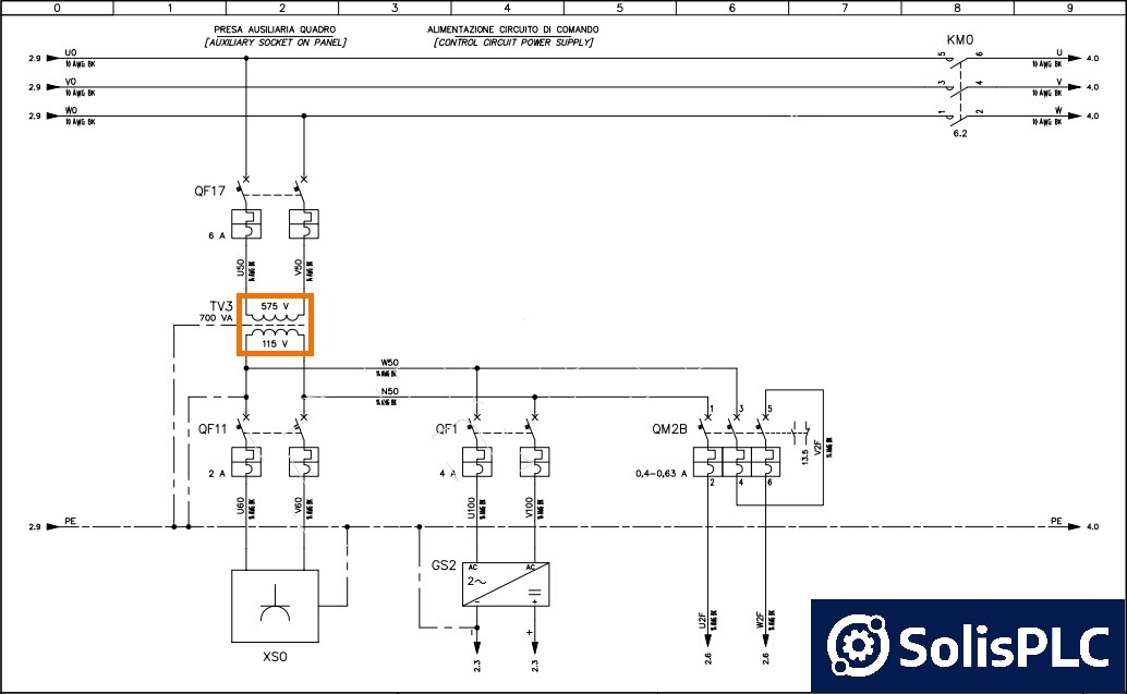
Understanding the wiring diagram of a motor control panel is essential for the successful operation of any kind of machinery. A motor control panel is a device used to control the motors that are used in various industrial machines, including lathes, drills, and conveyor systems. Without a motor control panel, it would be difficult to control the speed, direction, and other factors of these machines.
A motor control panel wiring diagram is a visual representation of how the components of the motor control panel are connected. It shows what wires go where and how they’re connected. The diagram is essential for troubleshooting any issues with the motor control panel, such as a malfunctioning motor or faulty wiring.
The wiring diagram of a motor control panel is usually relatively straightforward. It consists of several diagrams that show the connections between each component of the motor control panel. The diagrams typically include pictures of the motor, motor control panel, and other components, as well as labels for each of the wires.
When reading a motor control panel wiring diagram, it’s important to pay attention to the symbols used. For example, a dashed line indicates a connection between two components, while a solid line indicates a direct connection. Additionally, arrows indicate the direction of power flow, while circles indicate the current source.
In order to properly interpret the wiring diagram, it’s important to understand the different symbols and their meanings. This can help to ensure that the connections between the components of the motor control panel are correctly made. If any of the connections are incorrect, it could lead to serious damage or malfunctions.
To ensure that a motor control panel is wired correctly, it’s important to follow the instructions provided in the wiring diagram. This can help to ensure that the motor and other components of the motor control panel operate efficiently and safely. Additionally, if any issues arise, the wiring diagram can be used to troubleshoot the problem.
By understanding the wiring diagram of a motor control panel, it is possible to ensure that the motor control panel is correctly wired and functioning properly. This can help to prevent any malfunctions or damage to the motor and other components of the motor control panel. Additionally, if any issues arise, the wiring diagram can be used to troubleshoot the problem.

How To Read The Electrical Diagram And What Are Symbols Involved In It Instrumentation Control Engineering

Basic Start Stop Ac Motor Control Schematics Ecn Electrical Forums

Three Phase Submersible Pump Control Panel Ats 10 Hp At Rs 18500 D Colony Ahmedabad Id 3030577230

Ac Motor Control Circuits Worksheet Electric

Motor Control Circuit Wiring Inst Tools
Motor Control And Wiring Diagram S Facebook
Electrical Control Panel What It Is And Why You Need One Panels Automation Systems

H1 Align Center Enotes Mechatronics And Controls

Dc Variable Sd Motor Control

Electrical Panel Wiring Diagram
Motor Control Starters Magnetic Starter C3controls

Submersible Pump Microcontroller Wiring Diagram Three Phase Electric Power Control Environment Electronics Electrical Wires Cable Relay Png Pngwing

Basic Wiring For Motor Control Technical Data Guide Eep

Circuit Breaker Car Wiring Diagram Electric Motor Tachometer Electronics Electrical Wires Cable Png Pngwing

Basic Wiring For Motor Control Technical Data Guide Eep

Mastering Motor Control Center Mcc Wiring Diagrams And Equipment From Zero To Hero Eep

The Dc Counter Emf Motor Controller And Variable Sd Drives

All About Wiring Of Electric Motors Eep

Electric Motor Control Wiring Methods Electrical A2z

How To Read A Plc Wiring Diagram Control Panel Upmation

