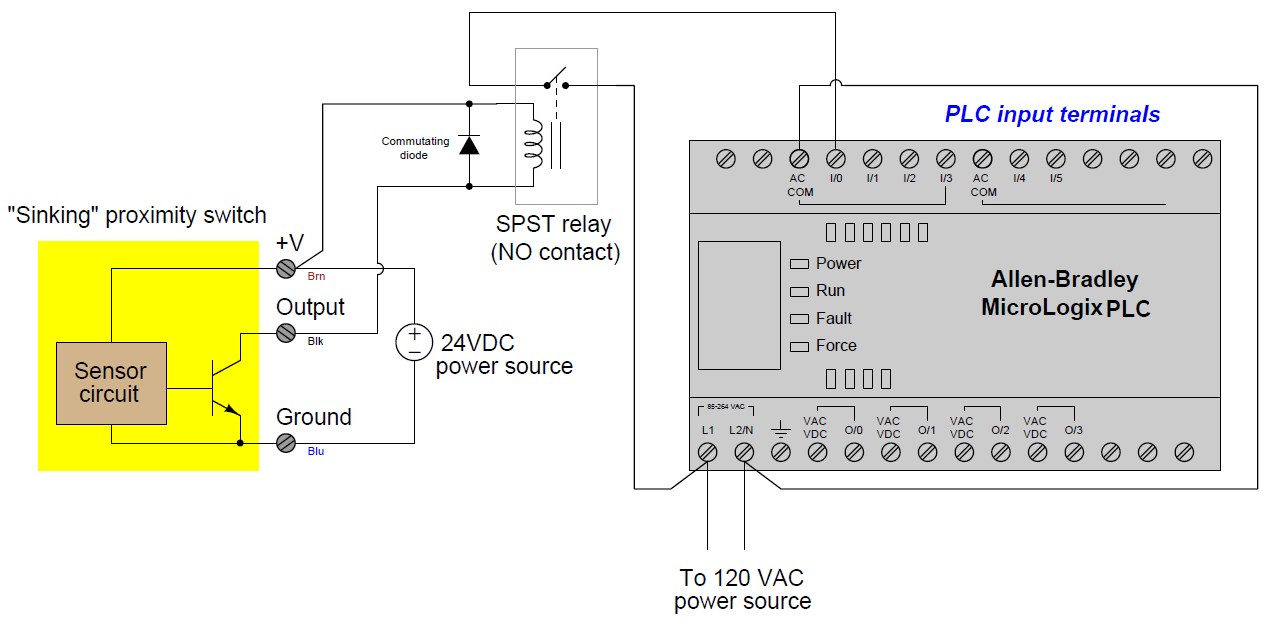
Plc Relay Wiring Diagrams: The Basics of Automation Control
If you're looking to understand the basics of automation control, then a Plc Relay Wiring Diagram is an invaluable tool. It provides a visual representation of how the various components of a system work together to produce the desired result. To get the most out of your automation system, it's important to have a good understanding of how a Plc Relay Wiring Diagram works.
Let's start by taking a look at what a Plc Relay Wiring Diagram is. Essentially, it is a schematic diagram that shows the connections between the various components in an automation control system. Typically, this includes relays, controllers, motors, power supplies, and other devices. By understanding how these components are connected, you can determine the best way to implement the automation system and implement it correctly.
When you first look at a Plc Relay Wiring Diagram, you may be overwhelmed with the amount of information it contains. However, once you understand its basic structure, it becomes much easier to make sense of it all. The key to understanding a Plc Relay Wiring Diagram is to focus on the primary components and their connections. This will allow you to identify any potential problems and make any necessary adjustments before implementing the system.
The main components of a Plc Relay Wiring Diagram are the relays, controllers, and power supplies. Relays control the flow of electricity between the different components. Controllers, on the other hand, regulate the speed, direction, and intensity of the current. Finally, the power supplies provide the voltage necessary for the components to function properly. Each component has its own unique wiring diagram, which must be followed precisely in order for the system to operate correctly.
In addition to the primary components, there are also several other elements that must be included in a Plc Relay Wiring Diagram. These include switches, resistors, capacitors, fuses, and circuit breakers. All of these components are necessary for the proper functioning of the system.
By understanding how the various components of a Plc Relay Wiring Diagram work together, you can ensure that your automation system operates correctly and efficiently. When you understand the basics of automation control, you'll be able to quickly identify and resolve any potential issues that arise. With a Plc Relay Wiring Diagram, you can rest assured that your automation system will run smoothly and efficiently, providing you with the ultimate control over your automation system.
Solved Draw An I O Wiring Diagram And Ladder Logic Program Chegg Com

Plc Wiring Example Engineers Community

External Wiring Diagram Of Plc Under Other Circuits 58663 Next Gr

How To Read A Plc Wiring Diagram Control Panel Upmation

Your Personal Plc Tutor Relay Outputs

Wet Contact Relay And Wiring Diagram Articleshook

Phoenix Contact Plc Rpt 110uc 21au Rw Interface Relay 10 Pc S Conrad Com

Relay Logic Vs Ladder World

Electronics Free Full Text Plc Hmi Based Implementation Of A Real Time Educational Power System Protective Relays Platform Html

How To Connect A Solenoid Valve With Plc Instrumentationtools

Basics Of The Plc Controllers Ladder Program Operations Blog Related To Automation Hmi Control Systems

What Is Interposing Relay In A Plc System Instrumentationtools

Wiring Diagrams Of Plc And Dcs Systems Di Do Ai Ao

Wiring Diagram Of Switches And Relays To The Plc Scientific

Schematic Diagram For Multiple I O Plc Modules Scientific

Wiring Plcs
Solved Ladder Diagram Is One Of The Programming Formats That Chegg Com

Safety Relays How And Where Work

China 8 Input Relay Output Plc With Microwin Program Programmable Logic Controller

