Introduction
A servo controller schematic is an essential component of any automated control system. It allows a robot or machine to accurately and efficiently respond to external stimuli, and can be used to achieve complex tasks with minimal input from a human operator. Servo controllers are used in a wide range of applications, from industrial automation to consumer electronics, and understanding how they work can help you create more effective and efficient automated systems. In this blog post, we'll explore the basics of a servo controller schematic, including its components and how it works.
The Components of a Servo Controller Schematic
A servo controller schematic typically consists of three main components: a power supply, a servo motor, and a controller board. The power supply provides the electrical energy needed to operate the servo motor, while the motor itself is responsible for converting the electrical energy into mechanical motion. Finally, the controller board is responsible for controlling the movement of the motor, typically by sending signals to the motor based on user input or external sensors.
How a Servo Controller Works
When a servo controller receives a signal from a user or external sensor, it sends a signal to the servo motor. The motor then responds by moving in the direction specified by the signal. Depending on the type of servo motor, the speed and accuracy of the motor’s response can vary significantly. For example, some servo motors can reach speeds of up to 200 rotations per minute, while others may be limited to much slower speeds.
Conclusion
Servo controller schematics are an essential component of any automated control system. They allow machines and robots to accurately and efficiently respond to external stimuli, enabling them to perform complex tasks with minimal input from a human operator. By understanding the components of a servo controller schematic and how it works, you can create more effective and efficient automated systems.

Arduino Servo Control Schematic Pyroelectro News Projects Tutorials

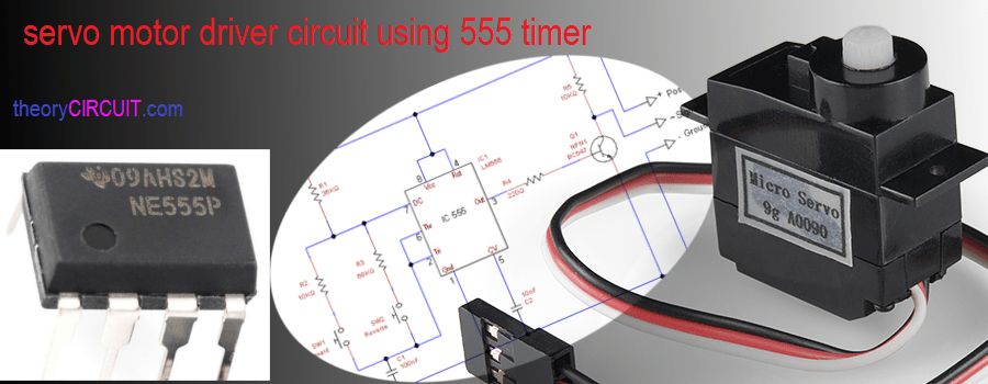
Servo Motor Driver Circuit Theorycircuit Do It Yourself Electronics Projects

Arduino Servo Motor Control Tutorial With Circuit Diagram And Code

How To Control Servo Motors With Arduino Complete Guide

Interesting Servo Control Circuit

How To Control Servo Motors With Arduino Complete Guide

How To Run A Servo Motor Using Ic 555 Homemade Circuit Projects

Pololu Simple Hardware Approach To Controlling A Servo

Circuit Zone Com Electronic Kits Projects Schematics Diy Electronics

Servo Motor Circuit Page 4 Automation Circuits Next Gr

Servo Motor Driver Circuit
Ntroller Circuit Diagram And Working Principle 1 Chegg Com

Lab 21 Servo Motor Control Embedded

Servo Motor Driver Circuit Using Ic 555 Gadgetronicx
Servo Controller Circuitlab

Servo Motor Circuit Page 3 Automation Circuits Next Gr

Servo Control Based On Motor Sd Tinkercad

Ac Servo Motor Controller Circuit Diagram

L Hexapod Books Archives