If you’re a professional electrician or know your way around wiring, then you’ve likely encountered a signal phase dol starter wiring diagram. Understanding these diagrams is essential for anyone attempting to wire these complex systems. This article will explain what a signal phase dol starter wiring diagram is, how it works, and why it should be carefully studied before attempting any kind of wiring job.
A signal phase dol starter wiring diagram is a visual representation of the wiring required to connect a motor to the necessary power sources. This diagram contains all the information needed to correctly wire the motor, including the necessary switches and circuit breakers. It also shows the direction of current flow and the way the signal phases need to be wired. While these diagrams can look daunting at first, they are actually quite simple and easy to understand once you know what each symbol represents.
The signal phase dol starter is essentially a three-phase motor with a built-in control circuit. This type of motor is often used in industrial applications, such as manufacturing and construction. The control circuit allows the motor to start and stop automatically, which helps to ensure that the motor runs efficiently and safely. The control circuit also allows the motor to be connected to multiple power sources, such as AC and DC.
When studying a signal phase dol starter wiring diagram, it is important to pay attention to the symbols used. Each symbol has a specific meaning, so it’s important to understand what each one stands for. The most common symbols are the power source (AC or DC), the motor, the circuit breaker, the switch, and the signal phase. Other symbols may include the direction of current flow, the coil, and the capacitor.
Once you understand the symbols used in the signal phase dol starter wiring diagram, it’s time to get to work. Before beginning any wiring project, it’s important to make sure that all the components are properly connected and that the proper safety protections are in place. Once everything is connected, the motor can be tested to make sure it is operating correctly.
Understanding signal phase dol starter wiring diagrams is critical for any electrician or wiring technician. By taking the time to study these diagrams and understanding the symbols used, you can ensure that any wiring project you undertake will be successful.

Direct On Line And Star Delta Starter Circuit Diagrams Overview 1683 Words Sment Example

Star Delta Starter Explained In Plain English Electrical4u

What Are Dol And Rdol Starters Advantages Disadvantages

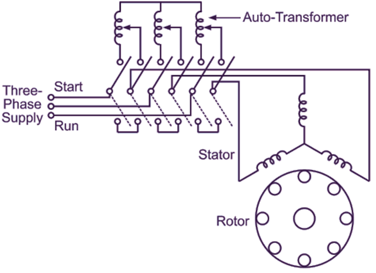
Autotransformer Starter Working Diagram Electricalworkbook

Dol Starter Direct Online Details Including Workign Principle Circuit Diagram Bdelectricity Com

Aim Manual Page 54 Single Phase Motors And Controls Motor Maintenance North America Water Franklin Electric
Indo Tech Electrical Dol Starter Without Neutral 3 Phase Facebook By Contactor Switch Timer Motor Listrik Phases

Three Phase Gsm Mobile Motor Pump Controller With All Safety Protection Alerts Timer Features

Star Delta Starter Explained In Plain English Electrical4u

Schematic Diagram Of Soft Starter Scientific

Direct Online Starter Dol Motor Circuit Diagram And Working Principle

Three Phase Dol Starter Voltage 220 440 V Rs 2000 Tamanna Electricals Id 14638342488

Electric Motor Starters What Are Types Of Electrical Automation Plc Programming Scada Pid Control System

Plc Implementation Of Forward Reverse Motor Circuit With Interlocking

Dol Starter Direct Online Working Diagram Electricalworkbook

3 Simulink Model Of Three Phase Induction Motor Direct On Line Starter Scientific Diagram

Dol Starter Direct Online Diagram Construction Advantages Electrical4u

Induction Motor Starter Types Circuit Diagram
