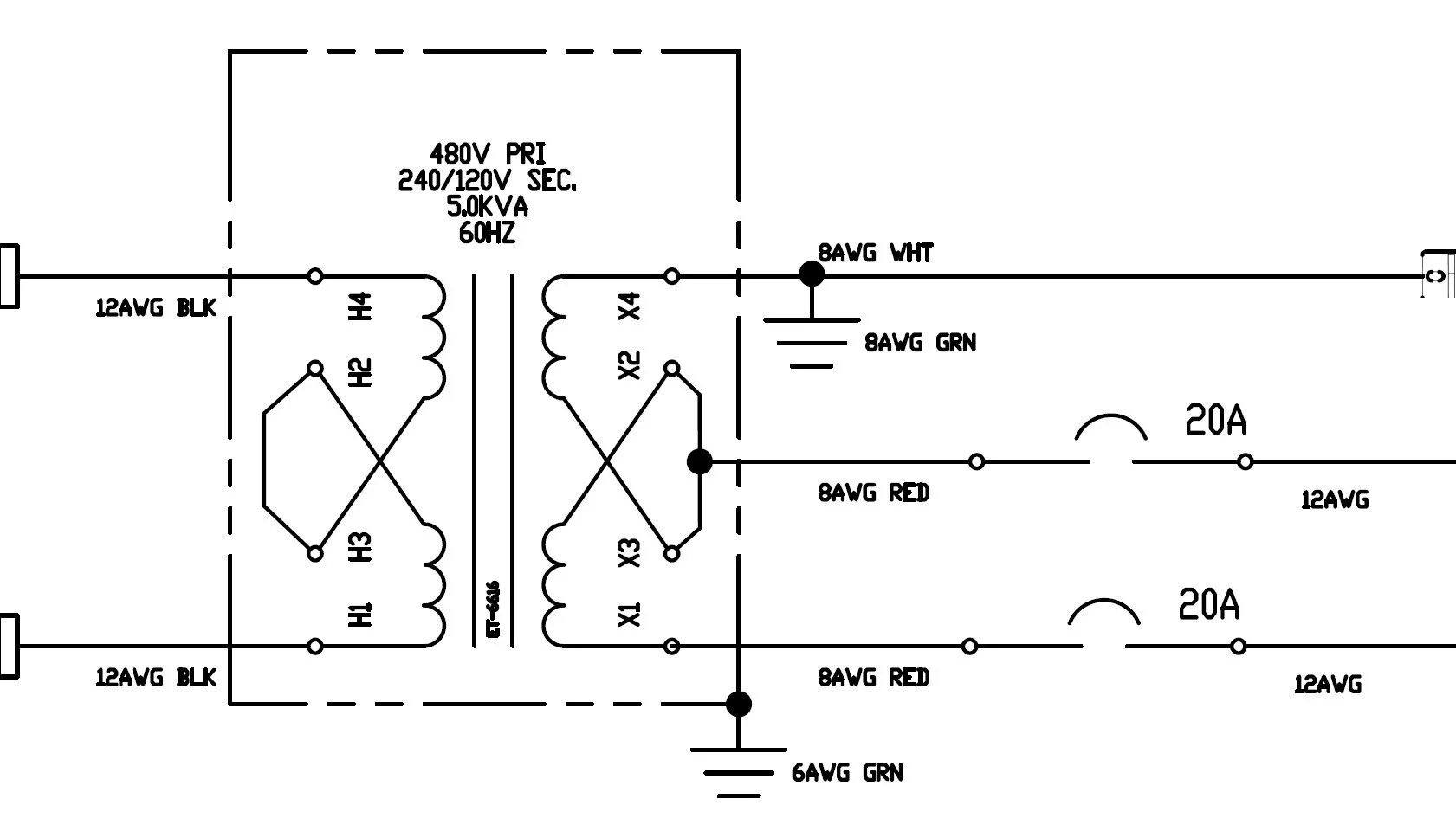
When it comes to electric power distribution, having a clear understanding of the transformer schematic is essential. This is especially true when it comes to single phase 480V, 240V, and 120V with neutral transformer schematics. Understanding this type of transformer schematic can help you make the right decisions when it comes to safely and effectively distributing power.
In this article, we'll take an in-depth look at single phase 480V, 240V, and 120V with neutral transformer schematics. We'll discuss how these systems are designed and why they are necessary for certain applications. We'll also examine how to read and interpret a single phase 480V, 240V, and 120V with neutral transformer schematic and provide some tips for troubleshooting any problems that may arise.
At its most basic level, a single phase 480V, 240V, and 120V with neutral transformer schematic consists of two coils, or windings, each connected to a voltage source. The primary winding is connected to the 480V voltage source and the secondary winding is connected to the 240V and 120V voltage sources. The neutral conductor is then connected to the common point between the two windings.
The purpose of the transformer is to convert the 480V voltage into two separate voltages: 240V and 120V. This allows the system to distribute electrical power to multiple locations while still providing the necessary power levels. Depending on the application, the transformer may also be used to step up or step down the voltage.
In order to read and interpret a single phase 480V, 240V, and 120V with neutral transformer schematic, it is important to understand the symbols used. For example, the "T1" symbol represents the primary winding, the "T2" symbol represents the secondary winding, and the "N" symbol represents the neutral conductor. In addition, the arrows pointing in and out of each symbol indicate the direction of current flow.
Once you understand the symbols, it is important to pay attention to the transformer's configuration. This will allow you to properly identify the primary and secondary windings, as well as the neutral conductor. It is also important to note the voltage and current ratings associated with each winding.
Finally, it is important to be aware of the safety considerations when working with a single phase 480V, 240V, and 120V with neutral transformer schematic. It is always best to consult with a licensed electrician before attempting any work on the system. Additionally, all safety precautions should be taken, such as wearing the proper protective gear and following all local and national electrical codes.
Understanding single phase 480V, 240V, and 120V with neutral transformer schematics is an essential part of ensuring safe and effective electrical power distribution. By taking the time to understand the components, symbols, and safety considerations of a single phase transformer schematic, you can ensure that your system operates smoothly and as intended.

Power Distribution Single Phase And Three Equipment

240v 3 Phase And Single Oem Panels

Grounding For Control Transformers Technical Articles

Tutorial Single Phase Modeling

Dae Smb350 Ul 8 B 24 Channels Multi Circuit Function Electric Meter Rs485 Controls

Common Electrical Services Pveducation Com

Neutral Bond In A Single Phase 480 Primary To 240 120 Secondary Mike Holt S Forum

Transformer Calculations Ec M

3 Phase Power Vs Single Oem Panels
Single Phase Transformer Connections The Electricity Forum

Understanding The Basics Of Delta Transformer Calculations Ec M

Cur Systems Ac Dc And Voltage Levels Basics You Must Never Forget Eep

Grounding For Control Transformers Technical Articles

Power Distribution Configurations With Three 3ph Lines

5s1f Low Voltage Transformer Encapsulated Dry Type 1 Phase 5kva 240x480v Primary 120 240v Secondary 3r Schneider Electric Usa
Transformer Basics Information Guide
Is It Possible To Power A Household Electric Range 240v From 3 Phase 120 240 Delta Transformer With Center Tap Coil Wild Leg Bare In Mind The Requires
Single Phase Transformer Connections The Electricity Forum

Cte In 240 110v Transformers Ecn Electrical Forums