Transformers are essential components in electrical circuits and are used to transfer energy from one circuit to another. For this reason, a transformer schematic diagram is an invaluable tool for any electrician or engineer. A good understanding of how a transformer works and how to read a transformer schematic diagram is essential for anyone working with electricity.
A transformer schematic diagram is a visual representation of the internal components of a transformer and the connections between them. It provides an easy way to see how a transformer works and to identify any potential problems. The diagram typically includes symbols to represent each component and to indicate the type of connection between them.
To understand a transformer schematic diagram, it is important to understand the basic parts of a transformer. A transformer consists of two coils of wire, called the primary and secondary windings. The primary winding is connected to the power source and the secondary winding is connected to the load. A core, usually made of metal, is placed between the two windings to help conduct the magnetic field generated by the primary winding.
The transformer schematic diagram will typically include labels for each component, such as the primary and secondary windings, the core, and the power source. It will also show which components are connected and how they are connected. This allows the user to easily identify any potential problems or areas that need attention.
In addition to the components of the transformer, the transformer schematic diagram will also include information about the voltage rating of the transformer and the maximum current that it can handle. This information is important for making sure that the transformer is operating within its limits and not drawing too much current. It is also important for ensuring the safety of anyone working with electricity.
By understanding a transformer schematic diagram, electricians and engineers can quickly and accurately identify any potential problems and make necessary repairs or adjustments. This ensures that the transformer is operating safely and efficiently, and that any electrical work is completed correctly.

Wiring Of Control Power Transformer For Motor Circuits Eep

Equivalent Circuit Of A Distribution Transformer Scientific Diagram

Equivalent Circuit And Phasor Diagram Of A Transformer

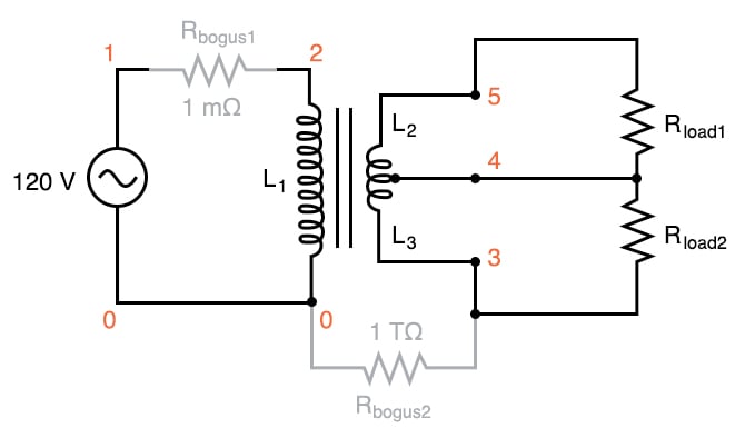
Transformer Power Supply Ac Circuits Electronics Textbook

The Equivalent Circuit Of A Practical Transformer Custom Coils

Cvt Constant Voltage Transformer Working Circuit Diagram Application

Center Tap Transformer Electronic Symbol Electronics Wiring Diagram Angle White Png Pngwing

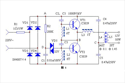
12v Electronic Transformer Circuit Diagram Principlehaisheng Electronics

Pulse Transformer Circuit Diagram Bdelectricity Com

Cur Transformer And Potential Circuit Diagram Working

Basic Electronics Transformers

What Is An Ideal Transformer Characteristics And Calculation Wira Electrical

How To Wire Install Isolation Transformer Ato Com

Potential Transformer 8 Important Topics Asked In Exams

Transformer Power Supply Ac Circuits Electronics Textbook

Power Transformers Operating Theory Gowanda

Equivalent Circuit Of Transformer Referred To Primary And Secondary Electrical4u

The Aa8v 6146b Amplifier Power Supply Schematic Diagrams And Circuit Descriptions

Transformers