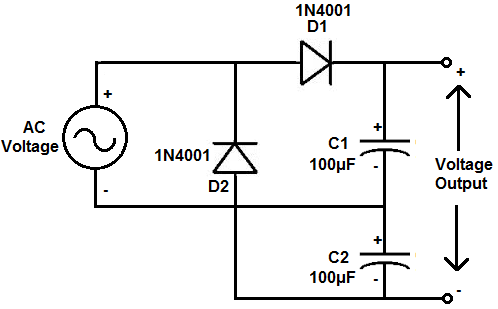
As technology advances, so does the need for more efficient and powerful circuits. The voltage doubler circuit is a great way to boost power and increase the efficiency of any circuit. This article will explore what a voltage doubler circuit is, how it works, and why it is becoming increasingly popular among circuit designers.
A voltage doubler circuit is a type of electrical circuit that enables an increase in the voltage level of a given signal. This is done by using two capacitors and one diode, connected in series with the circuit. A voltage doubler circuit can be used to double the voltage of a given signal, allowing higher power levels and increased efficiency.
The basic principle behind a voltage doubler circuit is to use two capacitors and one diode to “double” the voltage of a given signal. The two capacitors are connected in series, with the first capacitor storing energy and the second releasing it. The diode is connected between the two capacitors, enabling current to flow through the circuit only in one direction. When the input voltage is applied to the circuit, the first capacitor stores the energy and the second capacitor releases it. This process creates a doubled voltage level.
The advantages of using a voltage doubler circuit are many. Firstly, it is a simple and cost effective way to increase the power of a given signal. It also allows for higher efficiency as the voltage is “doubled” before being used in the circuit, reducing losses due to heat. Additionally, it can be used to increase the power of low-voltage signals, allowing them to be used in more powerful circuits.
In recent years, voltage doubler circuits have become increasingly popular among circuit designers. As technology advances, the need for more efficient and powerful circuits is growing, and the voltage doubler circuit is a great way to meet this need. It is also a great way to increase the efficiency of any circuit, as it can easily double the voltage of a given signal.
If you are looking for a way to increase the power and efficiency of your circuit, then a voltage doubler circuit may be the perfect solution. With its simple design and cost effectiveness, it is a great way to maximize the power of any circuit.

2 Easy Voltage Doubler Circuits Discussed Homemade Circuit Projects

12v To 24v Voltage Doubler Circuit Using Cd4049 Ic

Voltage Doubler Circuit Diagram Scientific

Difference Voltage Doubler Tripler Quadrupler

Voltage Doubler Basics

Voltage Doubler A Cheaper And Lighter Alternative To Transformer Rectifier Circuits

High Voltage

12v Voltage Doubler Circuit Under Repository Circuits 22155 Next Gr

Voltage Multipliers Half Wave Doubler Tripler Quadrupler D E Notes

Voltage Multipliers Half Wave Doubler Tripler Quadrupler D E Notes
Voltage Doubler Circuit
Voltage Doubler A Cheaper And Lighter Alternative To Transformer Rectifier Circuits

Voltage Doubler Circuit

Voltage Doubler Circuit Schematic Using 555 Op Amp Ac To Dc

Dc Voltage Doubler And Multiplier Circuits Working Eleccircuit

How To Build A Voltage Doubler Circuit

Voltage Doubler Circuit Schematic Using 555 Op Amp Ac To Dc
Rf Energy Harvesting Systems A Voltage Doubler Circuit B Equivalent Scientific Diagram

Diode Voltage Doubler Circuit With Tripler And Quadrupler Explained